The new Blue Line extension to the Washington, D.C.-area Metrorail system features steel bridges for cost savings and construction speed.
The first ever large-scale design-build project awarded by Washington Metropolitan Area Transit Authority (WMATA) is a 3.1 mile-long extension of the Blue Line on Washington D.C.’s Metro rail system. This extension is located in Prince George’s County, MD, east of the capital, and is the first Metrorail line in the county to extend past the Capital Beltway (I-495). The Largo Extension connects two new passenger stations to the Metrorail system—one at Morgan Boulevard and the other at Largo Town Center. The project also includes 2.2 miles of cut-and-cover tunnel construction, 0.6 miles of dual aerial structures, and the operations building. Only about 2.5% of the entire alignment (0.1 miles) is built at grade.
Going Design-Build
The Blue Line extension program was split into three major construction contracts: site preparation and beltway crossing; line, trackwork and systems; and stations and parking facilities. The first contract was advertised as a conventional design-bid-build project; the two remaining contracts were awarded as designbuild projects. Revenue operations of Metrorail trains are expected to begin in December 2004, less than three years after awarding the design-build contracts.
Design-build and steel were chosen to meet the project’s tight schedule. As the designer for the joint venture of Lane Construction, Granite Construction and Slattery Construction (LGS), Jacobs Civil provided construction documents for all structures, electrical facilities, mechanical facilities and track, and coordinated the installation of the automatic train control, traction power and communication systems to provide an operating segment in less than three years. This very tight schedule required that WMATA, LGS and Jacobs work as a team to agree on solutions that were cost effective and could be constructed efficiently. Based on these goals, the team selected steel structures.
By bringing the fabricator on-board at an early date, during the bidding process, the designer and installer were able to work together to develop a product that would permit accelerated delivery and erection of the aerial structures. During the final design stage, open communication between the designer, fabricator and erector made it possible to iron out steel details, plate sizes and job-specific quality issues months before the design drawings were released for construction. This helped the fabricator with the procurement and planning of the work and minimized RFIs and change orders.
Why Steel?
At the conceptual stage of the project, the aerial structures were envisioned as prestressed-concrete trapezoidal box girders supported over a concrete sub-structure. However, during the proposal process, the design-build team determined that steel superstructures would reduce the mobilization cost and enhance the construction schedule. The aerial portion of the project was not large enough to overcome the substantial initial investment necessary for segmental construction, even if all segments were designed with the same cross section and geometry. Due to the terrain and the presence of the features such as crossovers and turnouts, it was necessary to vary the deck geometry and span lengths.
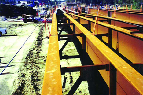
Under the circumstances, a welded steel plate-girder superstructure was more suitable than a concrete alternative, since it was adaptable to the design conditions. In view of the potential cost savings and an accelerated construction schedule, WMATA agreed to material substitution as long as steel met all of the required project design criteria. The State of Maryland’s preference for steel structures over major highways also was taken into consideration.
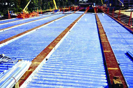
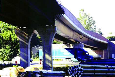
The Blue Line extension includes 37 spans of steel aerial structures. Thirty of them are single-track bridges preferred by WMATA to permit bypassing during emergencies, and for ease of maintenance and repairs. Five spans carry turnouts for future extensions in addition to the main tracks. Another two spans support double crossovers near Largo Town Center Station. The basic configuration of the single-track bridge is a two-girder system with a composite concrete deck. The rails attached with direct fixation devices are supported by reinforced concrete plinths poured separately in a top-down method. The two girder cross section is optimal for the 16′-to-18′ deck width required to accommodate a single track, cable troughs, safety walks and handrails while maintaining the minimally required horizontal clearances. A three-girder cross section was less economical, but allowed reduction in the depth of the superstructure; this type of cross section was used only on one of the spans where limited vertical clearance under the bridge required a shallower superstructure. Straight girders were used predominantly for steel framing, even at locations with circular or spiral alignment. The girder spacing was kept at 8′, except on spiral or curved alignments, where it was sometimes increased to up to 10’ to avoid uplift. Also, it was increased to avoid placing excessively high live loads on the girders. Horizontally curved steel tub girders were used at one location, where, due to the sharp curvature, a straight girder arrangement was not feasible.
Besides the three-girder system, there were other variations from the basic twogirder arrangement. At the doublecrossover location, three additional girders were used between the inbound and outbound tracks to form a common 62′-wide deck. At the turnouts for future Metro extension, splaying three or four girders was necessary to support the decks with varying widths. Immediately west of the Capital Beltway (I-495), a through-girder bridge was designed to accommodate the severely restricted vertical clearance under the crossing.
The majority of the aerial structures within the project have span lengths in the 120′ to 150′ range. The structures that fall beyond this range are the 76′-long through-girder bridge and the 324′-long, two-span continuous bridge across the Beltway. Selection of span type (simple versus continuous) was influenced by the vibration design criteria. This is generally not the case for highway bridges of similar composition, where economy can be derived from making the spans continuous. The vibration requirements also reflect on the end/interior-span length ratio for continuous-span transit structures. For highway bridges, economic considerations traditionally dictate that this ratio be kept around 0.8. Usually, it is not so for transit bridges. To limit potential dynamic interaction between aerial structure and the transit vehicle, WMATA design criteria require the unloaded natural frequency of the first mode of vibration to be no less that 2.5 Hz for simple-span structures, and no less than 3 Hz for continuous span structures. (Similar or slightly different criteria also exist for other transit systems/agencies.) Vibration limitations also allow the transit-vehicle peak vertical accelerations to remain within the accepted guidelines, which are related to passengers’ comfort and ride quality.
Expansion and ContractionSpherical bearings with high rotational capacities were chosen for the aerial structures. The bearings are arranged so that one pier has two fixed bearings followed by the next pier with two expansion bearings. Whenever possible, this kind of arrangement was selected to balance rail/structure interaction forces.
Rails are attached to the superstructure and to the subgrade or concrete track bed beyond the abutments by means of direct fixation fasteners. As a result of temperature variations (60°F rise or fall in temperature), continuously welded rails are assumed to develop thermal stresses under zero-strain conditions. The relatively massive girders, on the other hand, develop negligible thermal stresses, but are subject to thermal elongation/contraction.
The direct-fixation fasteners connecting the rails to the superstructure act as springs until they develop a force of 3 kips under a displacement of 0.4″. Upon reaching this limit, fasteners are designed to allow the rail to slip while maintaining the 3 kips force.
These fastener-imparted forces are accumulated in rails, creating stretches of tension and compression in addition to the rail thermal forces. The resulting maximum forces in rails depend on span lengths and bearing arrangement. If in a succession of simple-span bridges, every fixed pier has equal span lengths on both sides, then the rail/structure interaction forces will be balanced completely and locked in the rails.
Similar assumptions of symmetry also are made for the continuous structures to keep the rail-structure interaction forces balanced. If the condition of symmetry in the superstructure is not satisfied, the unbalanced forces are transferred to the substructure elements. For tall and slender piers, this could be a problem, but for the massive and inflexible piers in the Blue Line Extension, the effect was practically negligible.
In a properly designed structure, the rail/structure interaction should not generate excessive force in the substructure, and should not overstress the rails. Thus, the magnitude of the interaction force in rails is a good measurement of the appropriateness of the span lengths and bearing arrangement. Analysis indicated the maximum rail force to be around 80 kips; well within 132 kips allowed by the WMATA design criteria.
Alternating fixed piers with expansion piers in a succession of simple span structures, while beneficial from the rail/structure interaction point of view, results in deck joints over the expansion piers that also exhibit the maximum thermal movements. This was the dilemma for the double crossover at the Largo Center Station. The 320′-long crossover extended beyond two 140′-long spans, and included three deck joints. All of them had to be designed for the minimum possible thermal movements. Therefore the above-described optimal bearing arrangement was compromised. The pier at the middle of the crossover was designed as a fixed pier, and the other two piers had a combination of the fixed and expansion bearings. As mentioned before, the WMATA rail/structure interaction requirement was still satisfied.
The design also was checked for emergency conditions, such as derailment and rail-break loadings. A derailed train was assumed to shift laterally as far as 3′ from its normal position and impose a 100% impact on the structure for two axles with a normal impact of 30% for the rest of the train. For rail-break forces, only one rail at a time was assumed to be broken under extreme condition of a temperature drop of 100°F.
Fatigue Factor
One of WMATA’s main concerns in the selection of superstructure material was its ability to withstand fatigue. WMATA specifically emphasized that details used in the design of the aerial structures would not be susceptible to fatigue cracking. Since the majority of the bridges are designed as two-girder systems, all girders (main-load carrying members) and their fasteners are considered non-redundant load-path structures—that is, where failure of a single element could cause collapse of the structure. Accordingly, the allowable stress ranges indicated in AASHTO Table 10.3.1A for non-redundant load-path structures were used in proportioning the girders.
WMATA rapid-transit loading with full impact is used to determine the magnitude of stress range for 3 million cycles over the life of the structure in order to ensure that the maximum stress-range cycles will fall below the fatigue limit for all service conditions. The weld details for the diaphragm connection plates and transverse stiffeners are made in a way that no significant out-of-plane deformations will develop and their fatigue resistance would correspond to Category C. Bearing stiffeners are made out of 11/2”-thick or 1”-thick plates. Their connections to bottom-flange plates, where large, concentrated live load reaction forces are transferred, are made with partial-penetration welds.
Although the stiffeners are milled to bear, the concentrated cyclic compression occurring in a region of high-tensile residual stress makes this area vulnerable to fatigue cracking. There are also fabrication tolerances that can result in small gaps between the stiffeners and the bottom-flange plates. To avoid these situations, partial-penetration welds are used instead of fillet welds.
ASTM A709 grade 50W steel was used throughout the superstructure. The primary load-carrying components subjected to tensile stresses also were supplied to meet the additional requirements for the Charpy V notch testing requirements of AASHTO.
Aerial structures for WMATA’s Blue Line extension required some special design considerations that are not normally encountered/followed in typical highway- bridge design. By making a few prudent design decisions, composite steel superstructures proved to be a good choice for this design-build project.
Gautam Ghosh, P.E, S.E is a senior structural engineer/project manager with Jacobs Civil. Dan Korzym is a senior project manager with the Washington Metropolitan Area Transit Authority. Gregory Mester, P.E. is senior project manager and Alexander Rosenbaum, Ph.D., P.E. is chief structural engineer for Jacobs Civil’s Arlington, VA office.
Design-Build Contractor/CM
Lane Construction Corporation, Meriden, CT; Granite Construction Company, Inc., Watsonville, CA; Slattery Skanska, Inc., Whitestone, NY—A joint venture (LGS)
Structural Engineer
Jacobs Civil, Arlington, VA
Beltway Crossing Bridge
CTC/Wallace Montgomery & Associates, Towson, MD
Dynamic Analysis
David N.Wormley, Penn State
Engineering Software
STAAD Pro
GT STRUDL
MERLIN-DASH
DESCUS
Engineering Subconsultant
Tuhin Basu and Associates, Inc., McLean, VA